- 1)
- Also available as angled type, product numbers on request.
013-02
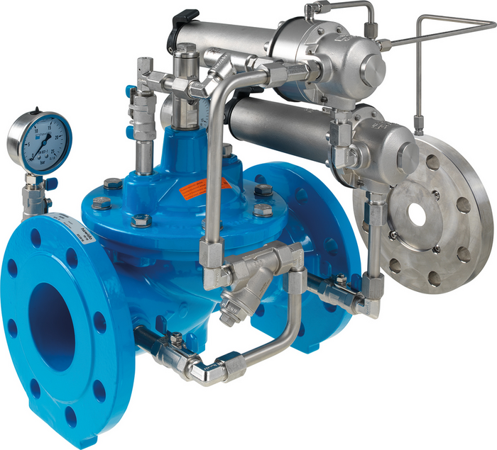
Flow control / limiting valve with pressure reduction
| Material: |
Body parts, orifice plate, housing: stainless steel, Hawle epoxy powder coated Control line, orifice plate: stainless steel Diaphragms, gaskets: EPDM acc. to KTW-BWGL for water Pilot valves: stainless steel |
|---|---|
| Max. operating Pressure: | See table |
| Medium | Water |
The flow control / limiting valve limits a preset max. flow from a higher pressure zone to a lower pressure zone, independent of varying operating pressures. The nominal flow is infinitely adjustable via the pilot valve up to +/- 15%. The additional pressure reducing function reduces a variable inlet pressure to a constant outlet pressure
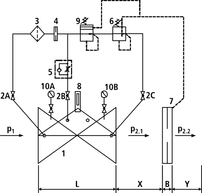
Minimum inlet pressure: 1 bar (Please consider: pressure loss due to main valve and orifice approx. 0.5 bar)
Make sure to allow for flow calming sections between the main valve and the orifice plate (x = 5 x DN) and downstream of the orifice plate (y = 3 x DN)!
For rating, please specify the following:
- Flow rate to be limited
- Inlet pressure (P1 side)
- Outlet pressure (P2 side)
Components:
1: main valve
2: ball valve (A, B, C)
3: filter
4: orifice
5: throttle check valve
6: pilot valve differential pressure measurement
7: differential pressure measuring orifice plate
8: optical position indicator with vent plug (option: electric position indicator, opening limiter)
9: pilot valve pressure reduction
10: manometer with ball valve (A, B)
B: DN 40- DN 150: 22 mm
DN 200 - DN 250: 27 mm
DN 300: 29 mm
X: 5 x DN pipe
Y: 3 x DN line
|
Order Nr.
|
*) |
DN |
Operating pressure max. |
PN |
L |
Medium | Weight | Specification | Basket |
|---|---|---|---|---|---|---|---|---|---|
|
130200400
|
IG 1 1/2" | Potable water: 16 bar | 10/16 | 210 mm | 11,00 kg | ||||
|
130200410
|
IG 2" | Potable water: 16 bar | 10/16 | 210 mm | 11,00 kg | ||||
|
130204010
|
40 | Potable water: 16 bar | 10/16 | 200 mm | 16,00 kg | ||||
|
130205010
|
1) | 50 | Potable water: 16 bar | 10/16 | 230 mm | 16,00 kg | |||
|
130206510
|
65 | Potable water: 16 bar | 10/16 | 290 mm | 21,00 kg | ||||
|
130208010
|
1) | 80 | Potable water: 16 bar | 10/16 | 310 mm | 27,00 kg | |||
|
130210010
|
1) | 100 | Potable water: 16 bar | 10/16 | 350 mm | 35,00 kg | |||
|
130212510
|
125 | Potable water: 16 bar | 10/16 | 400 mm | 52,00 kg | ||||
|
130215010
|
1) | 150 | Potable water: 16 bar | 10/16 | 480 mm | 76,00 kg | |||
|
130220010
|
1) | 200 | Potable water: 10 bar | 10 | 600 mm | 115,00 kg | |||
|
130220020
|
200 | Potable water: 16 bar | 16 | 600 mm | 115,00 kg | ||||
|
130225010
|
250 | Potable water: 10 bar | 10 | 730 mm | 247,00 kg | ||||
|
130225020
|
250 | Potable water: 16 bar | 16 | 730 mm | 247,00 kg | ||||
|
130230010
|
300 | Potable water: 10 bar | 10 | 850 mm | 265,00 kg | ||||
|
130230020
|
300 | Potable water: 16 bar | 16 | 850 mm | 265,00 kg |
-
PN 25 on request (up to DN 200)
|
Further information
|
|---|
| General instruction for Control Valves & Strainers |
|
Article Nr.
|
Product description |
|---|---|
| 019-00 | Strainer, lateral cover |
| 019-01 | Strainer with angle seat |
| 850-00 | Dismantling piece with restraint flanges |