- 1)
- Also available as angled type, product numbers on request.
013-06
Flow control / limiting valve with float control

| Material: |
Body parts, orifice plate, housing: stainless steel, Hawle epoxy powder coated Control line, orifice plate: stainless steel Diaphragms, gaskets: EPDM acc. to KTW-BWGL for water Float control valve: rstainless steel |
|---|---|
| Max. operating Pressure: | See table |
| Medium | Water |
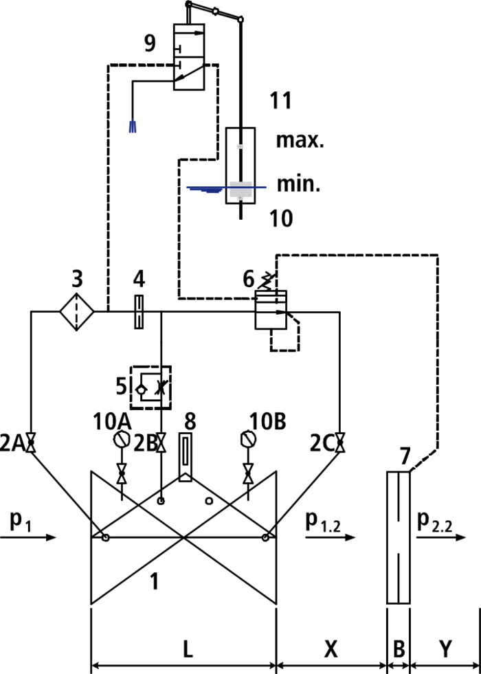
The flow limit / control valve limits a predetermined max. flow into a tank, independent of varying operating pressures and considering the water level in the tank. The nominal flow is infinitely adjustable via the pilot valve up to +/- 15%. If the maximum water level in the tank is reached, the main valve is closed. To avoid water hammers, the closing rate can be adjusted via the throttle check valve. The difference between minimum and maximum water level can be adjusted between 60 and 900 mm via the stops at the float rod.
Minimum inlet pressure: 1 bar (Please consider: pressure loss due to main valve and orifice approx. 0.5 bar)
Make sure to allow for flow calming sections between the main valve and the orifice plate (x = 5 x DN) and downstream of the orifice plate (y = 3 x DN)!
For rating, please specify the following:
- Flow rate to be limited
- Inlet pressure (P1 side)
- Outlet pressure (P2 side)
- Difference between min. and max. tank level
Components:
1: main valve
2: ball valve (A, B, C)
3: filter
4: orifice
5: throttle check valve
6: pilot valve
7: differential pressure measuring orifice plate
8: optical position indicator with vent plug (option: electric position indicator, opening limiter)
9: float valve
10: float
11: float protection tube (option)
12: manometer with ball valve (A, B)
B: DN 40- DN 150: 22 mm
DN 200 - DN 250: 27 mm
DN 300: 29 mm
X: 5 x DN pipe
Y: 3 x DN pipe
|
Order Nr.
|
*) |
DN |
Operating pressure max. |
PN |
L |
Medium | Weight | Specification | Basket |
|---|---|---|---|---|---|---|---|---|---|
|
130600400
|
IG 1 1/2" | Potable water: 16 bar | 10/16 | 210 mm | 11,00 kg | ||||
|
130600410
|
IG 2" | Potable water: 16 bar | 10/16 | 210 mm | 11,00 kg | ||||
|
130604010
|
40 | Potable water: 16 bar | 10/16 | 200 mm | 16,00 kg | ||||
|
130605010
|
1) | 50 | Potable water: 16 bar | 10/16 | 230 mm | 16,00 kg | |||
|
130606510
|
65 | Potable water: 16 bar | 10/16 | 290 mm | 21,00 kg | ||||
|
130608010
|
1) | 80 | Potable water: 16 bar | 10/16 | 310 mm | 27,00 kg | |||
|
130610010
|
1) | 100 | Potable water: 16 bar | 10/16 | 350 mm | 35,00 kg | |||
|
130612510
|
125 | Potable water: 16 bar | 10/16 | 400 mm | 52,00 kg | ||||
|
130615010
|
1) | 150 | Potable water: 16 bar | 10/16 | 480 mm | 76,00 kg | |||
|
130620010
|
200 | Potable water: 10 bar | 10 | 600 mm | 115,00 kg | ||||
|
130620020
|
200 | Potable water: 16 bar | 16 | 600 mm | 115,00 kg | ||||
|
130625010
|
250 | Potable water: 10 bar | 10 | 730 mm | 247,00 kg | ||||
|
130625020
|
250 | Potable water: 16 bar | 16 | 730 mm | 247,00 kg | ||||
|
130630010
|
300 | Potable water: 10 bar | 10 | 850 mm | 358,00 kg | ||||
|
130630020
|
300 | Potable water: 16 bar | 16 | 850 mm | 358,00 kg |
-
PN 25 on request (up to DN 200)
|
Further information
|
|---|
| General instruction for Control Valves & Strainers |
|
Operating instructions
|
|---|
| Operating and maintenance instructions - Flow control / limiting valve with float control |
|
Article Nr.
|
Product description |
|---|---|
| 013-08 | Float protection tube including assembly set |
| 019-00 | Strainer, lateral cover |
| 019-01 | Strainer with angle seat |
| 850-00 | Dismantling piece with restraint flanges |