- 1)
- Also available as angled type, product numbers on request.
017-08
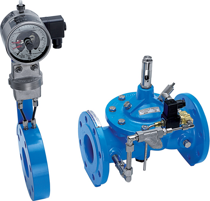
Pipe-break safety valve, electric control
| Material: |
Body parts, orifice plate, housing: GJS-400, Hawle epoxy powder coated Control line, orifice plate: stainless steel Diaphragms, gaskets: EPDM Solenoid valve: red brass, stainless steel |
|---|---|
| Max. operating Pressure: | See table |
| Medium | Water |
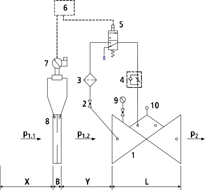
The electrically controlled pipe-break safety valve monitors the volume flow rate via the differential pressure measuring orifice (8). In case of a pipe burst the volume flow rate is increased, the pressure difference at the differential pressure measuring orifice (8) gets higher, and the differential pressure switch (7) responds. Via an electric control (not included in the scope of supply) voltage is applied to the solenoid valve (6), the solenoid valve is switched, and the main valve is closed. Via the throttle check valve (4) the valve closing rate can be adjusted
.
Minimum inlet pressure: 1 bar (Please consider: pressure loss due to main valve and orifice approx. 0.5 bar)
Make sure to allow for flow calming sections upstream of the orifice plate (x = 5 x DN) and between the orifice plate and the main valve (y = 3 x DN)!
For rating, please specify the following:
- Max. permitted flow rate
- Inlet pressure (P1 side)
- Outlet pressure (P2 side)
- Voltage (e.g. 24 V / 230 V)
- Type of current (alternating/direct current)
Components:
1: main valve
2: ball valve
3: filter
4: throttle check valve
5: electric solenoid valve
6: electric control (to be provided by the customer)
7: differential pressure switch
8: differential pressure measuring orifice plate
9: manometer with ball valve
10: optical position indicator with vent plug (option: electric position indicator, opening limiter)
B: DN 40-150: 40 mm
DN 200-300: 44 mm
X: 5 x DN pipe
Y: 3 x DN pipe
|
Order Nr.
|
*) |
DN |
Operating pressure max. |
PN |
L |
Medium | Weight | Specification | Basket |
|---|---|---|---|---|---|---|---|---|---|
|
170806510
|
65 | 16 bar | 10/16 | 290 mm | 27,50 kg | ||||
|
170808010
|
1) | 80 | 16 bar | 10/16 | 310 mm | 27,50 kg | |||
|
170810010
|
1) | 100 | 16 bar | 10/16 | 350 mm | 40,00 kg | |||
|
170812510
|
1) | 125 | 16 bar | 10/16 | 400 mm | 60,00 kg | |||
|
170815010
|
1) | 150 | 16 bar | 10/16 | 480 mm | 65,00 kg | |||
|
170820010
|
200 | 10 bar | 10 | 600 mm | 118,00 kg | ||||
|
170820020
|
200 | 16 bar | 16 | 600 mm | 118,00 kg | ||||
|
170825010
|
250 | 10 bar | 10 | 730 mm | 254,00 kg | ||||
|
170825020
|
250 | 16 bar | 16 | 730 mm | 254,00 kg | ||||
|
170830010
|
300 | 10 bar | 10 | 850 mm | 358,00 kg | ||||
|
170830020
|
300 | 16 bar | 16 | 850 mm | 358,00 kg |
-
PN 25 on request (up to DN 200)
|
Article Nr.
|
Product description |
|---|---|
| 011-03 | Power limitation module / plug-in module PLMV 24 V DC or 48-230 V DC/AC |
| 019-00 | Strainer, lateral cover |
| 019-01 | Strainer with angle seat |
| 850-00 | Dismantling piece with restraint flanges |