- 1)
- Also available as angled type, product numbers on request.
017-09
Pipe-break safety valve, hydraulic control

| Material: |
Body parts, orifice plate, housing: stainless steel, Hawle epoxy powder coated Control line, orifice plate: stainless steel Diaphragms, gaskets: EPDM acc. to KTW-BWGL for water Solenoid valve: stainless steel |
|---|---|
| Max. operating Pressure: | See table |
| Medium | Water |
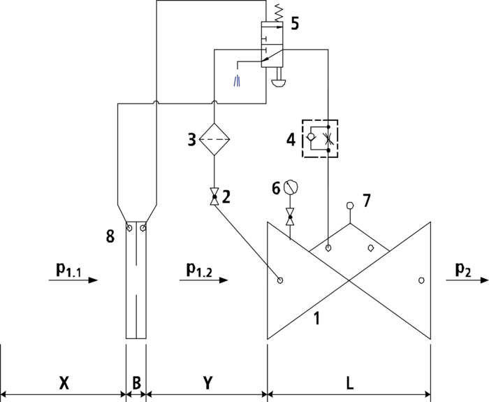
The hydraulically controlled pipe-break safety valve monitors the volume flow rate via the differential pressure measuring orifice (8). In case of a pipe burst the volume flow rate is increased, the pressure difference at the differential pressure measuring orifice (8) gets higher. The pipe-break safety pilot valve (5) is changed over and the base valve is closed. Via the throttle check valve (4) the valve closing rate can be adjusted.
Minimum inlet pressure: 1 bar (Please consider: pressure loss due to main valve and orifice approx. 0.5 bar)
Make sure to allow for flow calming sections upstream of the orifice plate(x = 5 x DN) and between the orifice plate and the main valve (y = 3 x DN!
For rating, please specify the following:
- Max. admissible flow rate
- Inlet pressure (P1 side)
- Outlet pressure (P2 side)
Components:
1: main valve
2: ball valve (A, B, C)
3: filter
4: throttle check valve
5: pilot valve
6: manometer with ball valve
7: optical position indicator with vent plug (option: electric position indicator, opening limiter)
8: differential pressure measuring orifice plate
B: DN 40-150: 40 mm
DN 200-300: 44 mm
X: 5 x DN pipe
Y: 3 x DN pipe
|
Order Nr.
|
*) |
DN |
Operating pressure max. |
PN |
L |
Medium | Weight | Specification | Basket |
|---|---|---|---|---|---|---|---|---|---|
|
170910010
|
1) | 100 | Potable water: 16 bar | 10/16 | 350 mm | 35,00 kg | |||
|
170912510
|
125 | Potable water: 16 bar | 10/16 | 400 mm | 51,00 kg | ||||
|
170915010
|
1) | 150 | Potable water: 16 bar | 10/16 | 480 mm | 76,00 kg | |||
|
170920010
|
200 | Potable water: 10 bar | 10 | 600 mm | 115,00 kg | ||||
|
170920020
|
200 | Potable water: 16 bar | 16 | 600 mm | 115,00 kg | ||||
|
170925010
|
250 | Potable water: 10 bar | 10 | 730 mm | 250,00 kg | ||||
|
170925020
|
250 | Potable water: 16 bar | 16 | 730 mm | 250,00 kg | ||||
|
170930010
|
300 | Potable water: 10 bar | 10 | 850 mm | 351,00 kg | ||||
|
170930020
|
300 | Potable water: 16 bar | 16 | 850 mm | 351,00 kg |
-
PN 25 on request (up to DN 200)
|
Further information
|
|---|
| General instruction for Control Valves & Strainers |
|
Article Nr.
|
Product description |
|---|---|
| 019-00 | Strainer, lateral cover |
| 019-01 | Strainer with angle seat |
| 850-00 | Dismantling piece with restraint flanges |